Pipe Jacking / Microtunnelling
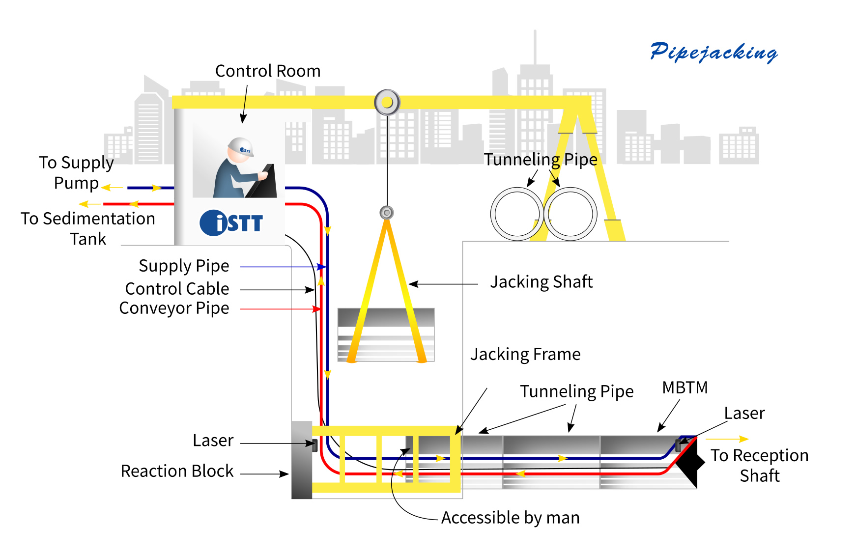
Pipe jacking is a tunneling method where a pipe being installed is used also as ground support during the tunneling operation. In this method, sections of pipe are lowered into the launching shaft and are thrust forward using jacks at the launching shaft as the tunnel advances. At the excavation face, a variety of equipment and configurations may be used according to the ground and groundwater conditions. In good ground conditions, a steel cylinder pushed ahead of the pipe sections provides immediate ground protection and the face may remain stable enough for hand or machine excavation without any special measure for face support. In more difficult ground conditions, partial face support or a closed excavation system using slurry for face support or an earth-pressure-balance (EPB) system may be required. The key difference from conventional tunneling is that the lateral ground support for the tunnel is provided by the pipes jacked from the launching shaft rather than the tunnel ground support being installed just behind the tunnel face. In pipe jacking, as the pipes are slid further and further through the ground, the frictional forces on the pipes lead to an increase in jacking loads that must be applied. This provides limitations on the length of individual pipe jacking installations that are not present in conventional tunneling. Nevertheless, long installations with pipe jacking are possible with the right preparations and equipment – with the longest single installation made to date being 2.5 km for a 3 m internal diameter pipe in Germany.
Microtunneling is a form of pipe jacking installation. It is defined as a remotely-controlled, guided, pipe-jacking operation that provides continuous support to the excavation face by applying mechanical or fluid pressure to balance groundwater and earth pressures. Support at the excavation face is a key feature of microtunneling, distinguishing it from traditional open-shield pipe-jacking. Microtunneling is used to install pipelines beneath highways, railroads, runways, harbors, rivers, and environmentally sensitive areas.
Originally, the term microtunneling was used to describe tunneling for tunnel diameters for which a person was not allowed to enter the tunnel (typically less than 0.9 m or 1.0 m). The term is now used also to describe the method (i.e. not requiring a person to enter) rather than a specific diameter range. Regional differences remain in the usage of the terminology.
The following detailed description is based on a slurry-type machine.
Microtunneling requires jacking and reception shafts at the opposite ends of each drive. The microtunneling process is a cyclic pipe jacking operation. A microtunnel boring machine (MTBM) is pushed into the earth by hydraulic jacks mounted and aligned in the jacking shaft. The jacks are then retracted and the slurry lines and control cables are disconnected. A product pipe or casing is lowered into the shaft and inserted between the jacking frame and the MTBM or previously jacked pipe. Slurry lines and power and control cable connections are made, and the pipe and MTBM are advanced another drive stroke. This process is repeated until the MTBM reaches the reception shaft. Upon drive completion, the MTBM and trailing equipment are retrieved and all equipment removed from the pipeline. Most microtunneling operations include a hydraulic jacking system to advance the MTBM and pipe string, a closed loop slurry system to transport the excavated spoils, a slurry cleaning system to remove the spoil from the slurry water, a lubrication system to lubricate the exterior of the pipe string during installation, a guidance system to provide line and grade control, an electrical supply and distribution system to power equipment, a crane to hoist pipe sections into the jacking shaft, and various trucks and loaders to transport spoil off site. MTBMs have a rotating cutting head to excavate the ground material, a crushing cone to crush larger particles into smaller sizes for transport through the slurry lines, a hydraulic or electric motor to turn the cutting head, a pressurized slurry mixing chamber behind the cutter head to maintain face stability, an articulated steering unit with steering jacks for steering corrections, various control valves, pressure gauges, flow meters, and a data acquisition system. Additionally, the MTBM has in-line cameras to relay information to the operator and a target system for guidance control.
Different ground control and muck transport systems may be used depending on the ground conditions, machine diameter, etc. Auger-based microtunneling systems have been used and earth-pressure-balance systems can be substituted for slurry systems in larger diameter microtunneling projects.
Precise control of line and grade is accomplished using the guidance system and steering jacks to locate and steer the MTBM during a microtunneling drive. The guidance system usually consists of a reference laser mounted in the jacking shaft, which transmits a beam onto a target mounted inside the articulated section of the MTBM. For curved microtunnel projects, gyroscopic survey systems combined with water level sensor systems (for vertical alignment) may be used. These data and other operational information are transmitted through wire cables to a control cabin located on the surface. Microtunneling machines are capable of independently counter-balancing earth and hydrostatic pressures. Earth pressure is counter-balanced by careful control of advance rates and excavation rates of spoil materials. Groundwater pressure is counter-balanced by using pressurized slurry in the soil-mixing chamber of the MTBM.
Valves, Safety Equip, Appurtenances
Underground utility systems contain a wide variety of operating components and monitoring and safety systems. The operational condition of all these appurtenances must be assessed during inspections to ensure the ongoing reliability of the system. Trenchless methods can play a role in such assessments but the variety of specific applications involved is not further explored here.
Vacuum Extraction
The excavated material at the face may be transported to the surface using a high powered vacuum or air pressure system. Such systems have been used since the 1980s with rock and consolidated ground conditions being the most favorable for their use. As the use of vacuum microtunneling systems has spread, they have increasingly been applied to a broad range of ground conditions and to larger tunnel diameters (up to 3m). Vacuum extraction may be used in single-pass microtunneling or in pilot tube applications (where it can be used for the pilot tube installation itself and/or for the subsequent boring operations).
Muck Cart
A muck cart is a traditional way of moving excavation spoil from the tunnel face to the starting shaft or entry point. Typically the cart is moved on rails and the tunnel is preferably excavated with a slightly uphill grade to aid in moving the loaded muck cart. Muck car systems are used in person-entry size tunnel diameters. In auger boring systems, a muck skip is used in the launch pit to receive the discharge from the auger.
Conveyor
Conveyor belt spoil removal systems are possible in person-entry tunnel diameters. They may be used with open face tunnelling systems or with an earth-pressure balance (EPB) system.
Spoil Handling
Spoil handling is an important method characteristic in microtunnelling and pipe jacking projects. For small diameter projects, the spoil or muck from the excavation face is removed in a slurry through a pipe to the surface or may simply be removed through a rotating auger back to the starting pit. In larger diameter tunnels, conveyor systems or muck cars on rails may be used. Excavation and muck removal systems may have the capability to deal with boulders up to a certain diameter by crushing such boulders into smaller fragments before they enter the rest of the muck removal system. When boulders exceed approximately one-third of the diameter of the microtunnel, they may not be able to enter either the crushing chamber for a slurry system or be able to pass through the auger in an auger system.
Slurry systems mix the excavated soil and rock into a mud slurry for pumping to the surface. For such systems, the excavated material must then be separated from the slurry using shakers and hydroclylones before disposal.
Other
Particularly in person-entry-scale pipe jacking, a variety of other face support measures (as are used in conventional tunnelling) are possible. These methods include mechanical breasting plates, sand shelves and partially closed faces.
Auger
Augers may be used as part of a face support system. For example, augers are typically incorporated as part of earth-pressure balance excavation systems. Continuous flight augers may provide little protection against soil loss in running ground below the water table but augers with different pitches can be combined to encourage a soil plug to be maintained within the auger system - thus allowing support to the excavation face.
Non-Person-Entry
A non-person-entry scale for pipe jacking represented an important part of the traditional definition of microtunnelling. The limitations presented by non-person-entry do have important implications for the tunnelling process - most importantly that there is no access to the face for changing cutter heads and inspecting/removing obstructions or maintaining tunnelling equipment.
Size
Size is an important distinction in pipe jacking and microtunnelling because, when there is no possibility for access to the tunnel face, there is no possibility to change cutterheads or remove obstacles ahead of the face without sinking a shaft from the surface. Also, in larger diameter microtunneling and pipe jacking projects, the jacking pipes have a great axial load carrying capacity and longer drives can be accomplished. Furthermore, smaller diameters for the tunnel affect the possibilities available for muck removal - with slurry systems and augers being used in the smaller diameters and conveyor systems or muck cars being possibilities in the larger diameters.
Person-entry pipe jacking allows a wide range of tunneling excavation and face support methods to be employed. Typically, a steel cylindrical tunnel shield is used at the face and is pushed ahead of the jacking pipes. Depending on tunnel size and ground conditions, various types of mechanical excavation equipment may be used and face support may include breasting plates, sand shelves and other forms of partial face support. Muck removal can be accomplished using a variety of methods – including muck cars or conveyor belts. Also, rectangular pipe jacking is becoming more widely used with its cross-sectional shape being particularly suitable for common utility tunnels or pedestrian underpasses.
Aboveground Surveys
Aboveground surveys can be used to search for evidence of leakage of buried pressure pipelines. These listen, look or monitor for any telltale signatures of leaks. The types of leak signatures possible depend on the nature of the pipeline and product transported. Examples include acoustic evidence of leaks from pressure pipelines, thermal effects from steam or hot water pipelines, vegetation changes (killed or more lush) and the presence of chemicals from the pipeline in the air or water environment near the pipeline. According to the nature and extent of the survey and the land use associated with the utility right-of-way, surveys may be able to be undertaken as aerial surveys, vehicle-based surveys, foot-traffic surveys or as discrete monitoring locations.
Person-Entry
Person-entry scale pipe jacking provides more options to address problems that may occur during the pipe jacking process. Access to the face is possible to inspect/remove obstructions, change cutterheads or maintain equipment.
Earth-Pressure Balance (EPB)
In the earth-pressure balance (EPB) system, the excavation face is supported by matching the spoil removal rate from the face with the advance rate of the boring machine. If the advance rate is too slow, over excavation may occur - allowing ground settlement. If the advance rate is too high, then under excavation may occur - potentially leading to ground heaving. To better control the pressure balance and smooth movement of excavation spoil, foam may be added to the face chamber in the boring machine.
Slurry
Pumping a mud slurry to the face chamber in a microtunnelling machine both allows the slurry pressure in the chamber to support the tunnel face and allows the excavated soil to mix with the slurry and be pumped to the ground surface via a return line. The excavated soil is then separated from the slurry and the slurry returned to the excavation face. A slurry system can be used in small diameter microtunnels but methods must be incorporated into the microtunnel machine to reduce the excavated material to a size that can be pumped through the slurry line.
Curved / Gyroscopic
For curved microtunnelling, gyroscopic systems may be used - involving a north-seeking gyro-compass to track horizontal alignment and a remote water level gauge system for vertical alignment. As the diameter of the tunnel increases other options involving automated target-seeking theodolites can be used for positioning in curved alignments and hand surveying can also be used. Where possible, hand surveying is often used periodically for calibration or quality control checks of automated systems.
Straight / Laser
For bores with a straight alignment, the standard method of guidance for microtunnelling is the use of a laser beam set in the starting shaft and a target placed towards the rear of the microtunnelling machine. The target may be an "active" target responding to the laser light hitting the target or a "passive" target where the position of the laser beam on the target is observed by a camera. Based on the information received from the guidance system, the machine operator can make steering corrections as the machine advances. Most commonly, steering is accomplished by adjusting the relative thrusts on a set of jacks between the front portion of the microtunneling machine and the remainder of the machine.
Alignment / Guidance
For bores with a straight alignment, the standard method of guidance for microtunnelling is the use of a laser beam set in the starting shaft and a target placed towards the rear of the microtunnelling machine. The target may be an "active" target responding to the laser light hitting the target or a "passive" target where the position of the laser beam on the target is observed by a camera. For curved microtunnelling, more sophisticated gyroscopic systems may be used - involving a north-seeking gyro-compass to track horizontal alignment and a remote water level gauge system for vertical alignment. As the diameter of the tunnel increases other options involving automated target-seeking theodolites can be used for positioning in curved alignments and hand surveying can also be used. Where possible, hand surveying is often used periodically for calibration or quality control checks of automated systems.
Based on the information received from the guidance system, the machine operator can make steering corrections as the machine advances. Most commonly, steering is accomplished by adjusting the relative thrusts on a set of jacks between the front portion of the microtunneling machine and the remainder of the machine.
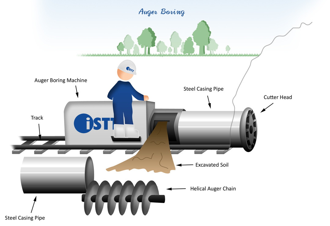
Auger Boring
Auger boring is generally used to install steel casing pipe in relatively soft stable ground conditions such as clay or soils with contained cobbles located above the water table. The auger boring process retains the soils within the casing, which reduces the likelihood of ground settlement from excavation, making auger boring a popular option for installing utilities under railroads, highways, and levies where settlement is a concern.The auger boring process employs an auger boring machine to rotate an auger chain or flight positioned within a casing pipe and fitted to a cutter head at the front of the casing. The rotating cutter head, which is slightly larger in diameter than the casing pipe, excavates the soil in front of the casing. The soil is transported back to the machine via the helical auger chain where the soil is removed by hand or machine. The auger boring machine advances along a track, which is aligned to drive the casing pipe on the designed installation line. Once the machine reaches the end of the track arrangement, the auger chain is disconnected from the machine and the machine is moved back to the original starting point on the track where a new casing segment is welded to the existing casing pipe, and a new auger chain connected to the machine and to the existing chain/cutter head. The excavation and thrust process is repeated until the project is completed. The auger chain is then withdrawn from the casing pipe and the pipe is cleaned of all remaining soil and ready to use.